Preface
In my first article, I discussed the differences between using the millis() function vs the delay() function when working with programs that require a timing implementation. The link to said article can be found at the bottom of this post.
For this article, we will be using the millis() function again to implement a software debounce for input signals. The input used for this example implementation will be a simple Normally Open (NO) pushbutton. However, this method can be applied to any other types of mechanically actuated input.
What Is Debouncing and Why Is It Necessary?
Before we get to debouncing, let's understand what "bounce" means.
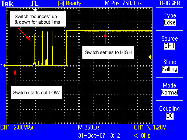
Bounce refers to the unpredictable rapid change of state that occurs before the signal settles to its intended state when a mechanical switch is depressed. This happens due to the vibration produced when the switch is activated. The vibration then causes the contacts of the switch to rapidly close and open the circuit which results in "bouncing". Figure 1.0 shows how an input signal behaves when "bounce" occurs.

Figure 1.
Bouncing may lead to a few problems for engineers. The most obvious problem is that the nature of the changes to the signal is unpredictable. This can lead to inaccurate switch behavior at best and a totally non-functional circuit at worst.
To remedy this issue, we have to "debounce" the switch. There are many methods available to debounce and these methods are generally divided into 2 categories: Hardware and Software debouncing.
Hardware debouncing usually involves using a capacitor to even out the bounce and produce a more gradual curve. Another method of hardware debouncing is to build a latching circuit. Some switches come with a built-in latch which gets rid of this problem all-together.
However, software debouncing is more commonly used as it can be implemented without any external circuitry or new components. Just like hardware debouncing, there are many methods available. We will take a look at one method which uses the millis() function which is a native function of the C++ language variation for the Arduino.
Circuitry

Above is the circuit I've built for demonstrating the debouncing method. The pin D2 serves as the input pin and the circuit is set up with a pull-down resistor configuration. When the pushbutton is not depressed, D2 will read a logical "0". This input circuit will control the output of D7 which is connected to an LED.
Debouncing Program
//Written by EthanH. 24/12/2023

const int buttonpin = 2;
const int ledpin = 7;

int buttonstate;
int buttonstateold = 0;

int ledstate = 0;

long prevtrig;
long debounceinterval = 50;

void setup() {
  // put your setup code here, to run once:
pinMode(buttonpin, INPUT);
pinMode(ledpin, OUTPUT);
}


void loop() {
  // put your main code here, to run repeatedly:
int reading = digitalRead(buttonpin);

if(reading != buttonstateold){
  prevtrig = millis();
}

if(millis() - prevtrig > debounceinterval){
  buttonstate = reading;
}

digitalWrite(ledpin, buttonstate);

buttonstateold = reading;
}
Above is the sketch used to debounce the input signal. Let's have a rundown of this program.
At the start of the program, 2 constant integers are declared (buttonpin, ledpin). These are declared as constants as they serve as the pin numbers on the board and will not be changed. The 2 are setup as an input and an output respectively in the void setup() function.
The next 2 integer variables (buttonstate, buttonstateold) are used to store the states of the pushbutton. The "buttonstate" variable stores the current state of the button while the "buttonstateold" variable stores the previous state of the button. One point to note is that these variables only store the state of the button. They are not the variables that are updated directly from the actual reading of the button state.
Similarly, the "ledstate" variable is used to store either a "1" or "0" state to be written to the LED.
The next 2 long variables are used to store amounts of time in milliseconds. The "prevtrig" variable is used to store the first output of the millis() function in the program and the "debounceinterval" variable stores a value of 50ms. The latter can be adjusted according to the needs of the user should they require a more stable debounce.
void loop() {
  // put your main code here, to run repeatedly:
int reading = digitalRead(buttonpin);

if(reading != buttonstateold){
  prevtrig = millis();
}

if(millis() - prevtrig > debounceinterval){
  buttonstate = reading;
}

digitalWrite(ledpin, buttonstate);

buttonstateold = reading;
}
The program runs by first getting the actual reading of pin D2. The value will be stored in the "reading" integer variable within the void loop() function.
When the button is pressed, the first if statement will execute since "reading" has been changed to "1" while "buttonstateold" still remains at "0" and the condition will become "True". The current time in milliseconds will then be stored in "prevtrig".
The second if statement will then acquire the current time in milliseconds and subtract it from the time stored in "prevtrig". If the result of this subtraction be greater than the declared "debounceinterval" value, the "buttonstate" variable will store the value from "reading" which will be a "1".
The "buttonstate" value will then be used to write to "ledpin". Since the value saved in "buttonstate" was a "1". The LED will be switched on.
After that is done, the current reading of the button (reading) will be saved to "buttonstateold".
Conclusion
This method of software debouncing provides an accurate input signal for the input pin of the Arduino by examining the consistency of the 5V signal during the debounce interval.
As mentioned above, this debounce interval may be adjusted if the duration is not big enough to produce the intended effect.
Since the millis() function was used in this implementation, the program will not have to be paused at any point.
Link to first article: ethanh.hashnode.dev/arduino-timing-implemen..
References
Fig 1.0. Image adapted from L3: Debouncing - Physical Computing (makeabilitylab.github.io)
